In this issue, we will explain how to install OTTO diy V1 to Sanwa Denshi JLF-TP-8YT series.I would like to describe how to install OTTO diy V1 to Sanwa Electronics JLF-TP-8YT series.
OTTO DIY V1 Set Contents

It is packed in this way. First, I will explain each part.
2 types of main guides

1.FD (square)
FD guides have rounded areas around the corners to make diagonal inputs easier to understand while allowing the top of the actuator to sit comfortably.
2.BFY(Semi-circular)
The BFY guide is for those who prefer octagonal guides. This is an excellent alternative than the octagonal guide.The rounded shape around the corners creates a smooth, semi-circular input feel while recognizing oblique input.
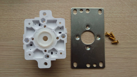
Modular Body

This is the part used to mount the pivot core, with a gold M3 nut embedded.
Enables mounting of Sanwa Denshi TP-MA PCB or HORI Microswitch PCB.
Pivot & Pivot Core

- Special shaped pivots, if you prefer quick input, go here. Pivots can be reversed to achieve two types of feedback; V1 is a very peppy pivot, so be sure to grease it liberally.

The pivot is tapered upward for a classical feel, so it returns to center faster.
Because the pivot is tapered upward, the feedback has a "peekier input feel" and is moreFaster return to center. - Pivot Core
Made of smooth Teflon material, it connects to the modular body. It is interchangeable with the V5 Teflon core and the V2 Corian-style grommet core.
Actuators & Screws

- 12mm, 12.5mm, and 13mm oversized actuators
Actuators are used to actuate each microswitch plunger. 12.5mm and 13mm actuators are designed to shorten the distance between the actuator and the plunger to speed actuation. - 2mm hexagonal gold thread
This screw replaces the existing screw used for mounting the Sanwa Denshi P-1 plate or the HoriHayabusa plate. A 2mm hexagonal wrench is required to install the screws.
The following is how to identify the actuator.

There is a hole on the inside, so please check there.
How to install the OTTO DIY V1 in the Sanwa Denshi JLF-TP-8YT series

Prepare JLF-TP-8YT series joystick.

Remove the shaft cover and dust washer.

Start working from the back side.

Main GuideGT-8FRemove the main guide GT-8F.

Remove the switch substrate TP-MA.

Remove the E-ring JLF-E.
The following video shows how to remove the E-ring. A dedicated tool is best, but a small flat-blade screwdriver can also be used to remove it.

Remove the actuator JLF-P-5.

Remove the spring JLF-SP.

Remove spring stopper JLF-P-6.

Remove the base washer JLF-MW.

Remove the main shaft JL-S9F.

Remove the flat steel plate JLF-P-1. The bolt part is glued on during removal, so it is recommended to warm it up with a heat gun or hair dryer before removal.
Be careful not to lick the screws if you try to remove it as it is.
JLF-TP-8YT seriesAfter disassembly

The parts disassembled up to this point are the parts used in OTTO DIY V1 on the left, and the parts not used on the right.
Assemble OTTO DIY V1.

Prepare OTTO DIY V1 pivot, pivot core, modular body, and screws.
Remove the Prepare also the flat iron plate JLF-P-1, grease to spread grease around the pivot.
The grease prepared this time is Shin-Etsu Chemical G501, because it is used in Seimitsu Kogyo's joysticks and for plastic lubrication.
Sanwa grease is Shin-Etsu Chemical G-40M, which is for high-temperature lubrication and general use. It will be suitable for lubrication of sealed bearings, please choose according to your preference.
Some people often use Tamiya's grease for mini 4WD and RC cars, but we do not recommend it because of its different application and viscosity.

Fit the pivot core into the modular body, apply grease to the pivot core area, and allow the grease to acclimate.
Snap the pivot into the pivot core.

Fit the flat iron plate JLF-P-1.

Fasten the gold screws with 2mm hexagonal screws.

Prepare spring stopper JLF-P-6.

Install the spring stopper JLF-P-6.

Prepare spring JLF-SP and select 12mm, 12.5mm, or 13mm size actuator.
This actuator selection will greatly affect the sense of operation.
The larger the size, the quicker and peppier the operation.
If the smoothness of the Teflon material is your main concern, choose 12 mm.

Once the actuator is decided, stop the E-ring JLF-E.

Prepare switch substrate TP-MA, FD (square) guide, and BYD (semicircular) guide.
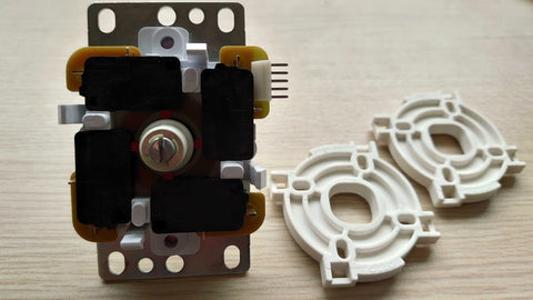
Set the switch substrate TP-MA.

Set the FD (square) guide or BYD (semicircular) guide whichever you prefer.
The sample image shows the BYD (semi-circular) guide.

Install the shaft cover and dust washer.

It's completed. Good job!
Change the settings to suit your preference and the title you play.


![ZERO ONE STICKLESS [All-Button]](http://us.akecon.games/cdn/shop/articles/Z1-AB-VM.png?v=1625924847&width=1)
